
Interferometry
Path difference and fringe count in a Michelson interferometer
The etendue non-sequential ray tracer compared with the worked examples of OpenStax University Physics, volume 3, section 3.6
Path difference and fringe count in a Michelson
interferometer
The etendue non-sequential ray tracer compared with the worked examples of OpenStax University
Physics, volume 3, section 3.6
| The question | The reference |
| Does etendue compute the optical path difference | The textbook gives two worked results. Moving one |
between the two arms of an interferometer correctly, to a mirror by 0.315 μm at 630 nm shifts the pattern by one
| small fraction of a fringe? A ray tracer that gets the path | fringe. A 2 cm cell filled with gas in one arm shifts it by |
| length wrong by a few nanometres would count fringes | 122 fringes at 632.8 nm, which gives a refractive index of |
| wrongly, and every interferometric result built on it would | 1.0019. Both follow from the path difference 2d₁ − 2d₂ |
| inherit the error. | between the arms. |
1 The system
Table 1. The interferometer as the textbook describes it. PART VALUE A collimated beam is split by a cube into two arms, each Source collimated, 5 mm radius, 100 rays, 630 nm closed by a flat mirror, and recombined on the detector. Beam splitter 25.4 mm cube, N-BK7, 50/50 The cube plays the part of the compensating plate: each Arms 100 mm from the splitter to each mirror beam crosses it twice, so both arms see the same thickness of glass. Mirror 2 is then moved along its arm, Gas cell 20 mm long in arm 2, n = 1.00193004 or a gas cell is placed in arm 2.
2 How far etendue is from the textbook
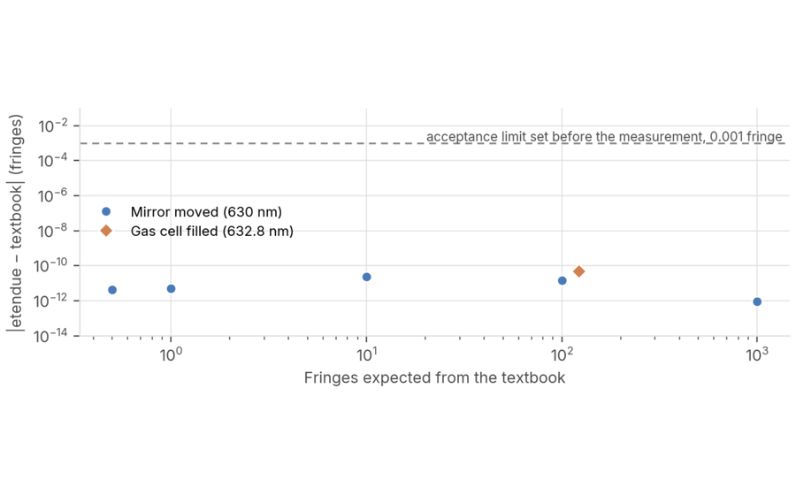
How large is the error on the fringe count? Ten orders of magnitude below the limit. Over a mirror travel of three decades, and through the filled gas cell, the path difference agrees with the textbook to the rounding of double-precision arithmetic.
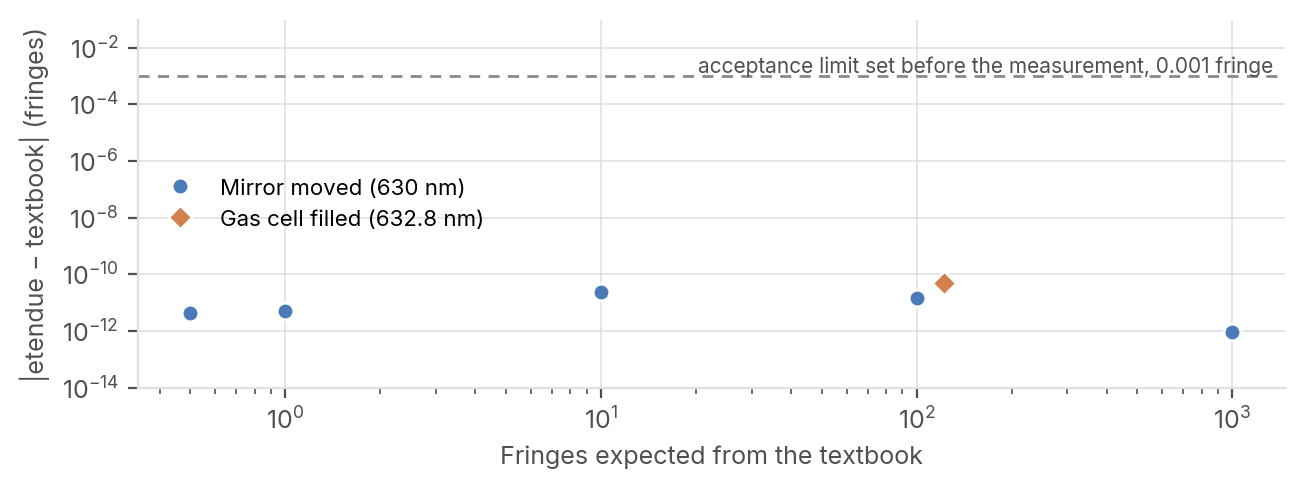
Figure 1. Difference between the fringe count computed by etendue and the textbook value, against the number of fringes expected. Circles: mirror 2 moved by 0.1575 to 315 μm at 630 nm. Diamond: gas cell filled at 632.8 nm. The dashed line is the acceptance limit, 0.001 fringe.
| 1.5×10⁻⁸ nm | 1.000000000 | 122.000000 | 14 of 16 |
| Largest error on the path | Fringes counted for the 0.315 | Fringes counted when the 2 | Comparisons within the limits |
| difference over six mirror | μm move of the textbook | cm gas cell is filled (122 in the | written before the |
| positions, from 0 to 315 μm. | example (1 expected). | textbook). | measurement. |
etendue.io Reference: S. J. Ling, J. Sanny, W. Moebs, University Physics Volume 3, OpenStax (2016), § 3.6 · etendue, November 2026
The numbers, and what they do not say
Every comparison, its limit, and the one configuration where etendue declines to answer.
Table 2. Path difference and fringes against the mirror displacement,
at 630 nm What this does not cover
The ray tracer gives one path Mirror Textbook moved (μm) (nm) etendue (nm) Error (nm) etendue fringes Intensity difference for each pair of rays that recombine. It does not draw the 0 0.0 0.000000 2.3×10⁻⁹ 0.000000000 1.000 circular fringe pattern or its 0.1575 315.0 315.000000 2.8×10⁻⁹ 0.500000000 0.000 contrast. Those come from the 0.315 630.0 630.000000 3.3×10⁻⁹ 1.000000000 1.000 wave model of the laser mode, 3.15 6,300.0 6,300.000000 1.5×10⁻⁸ 10.000000000 1.000 which is checked against the same textbook in a separate note. 31.5 63,000.0 63,000.000000 −9.5×10⁻⁹ 100.000000000 1.000 315 630,000.0 630,000.000000 5.8×10⁻¹⁰ 1000.000000000 1.000 The beam splitter is ideal in the textbook and no power is compared. The textbook path difference is twice the mirror displacement, and the textbook fringe count The gas is modelled, as in the is that path difference divided by 630 nm. The intensity is normalised to a bright fringe: 0 at a textbook, as a 20 mm column of quarter-wave move (dark fringe), 1 elsewhere. constant index without walls.
Table 3. The gas cell, at 632.8 nm
One case that is not met
Quantity Textbook etendue Error The interferometer of the project Fringes, cell filled with gas 122 122.000000000 −4.8×10⁻¹¹ library traces Fresnel reflections at Refractive index, four decimals 1.0019 1.0019 0 every glass face. 207 distinct beams then reach the detector, not the two Refractive index, unrounded 1.00193004 1.00193004 −6.7×10⁻¹⁶ of the textbook, and a single path Index error for 5 fringes miscounted about 8 × 10⁻⁵ 7.910 × 10⁻⁵ — difference is no longer defined. The index is n = 1 + mλ/(2t), with t = 20 mm. The textbook prints n to four decimals; the etendue refuses the reading and unrounded value follows from its 122 fringes. says why, instead of pairing two stray reflections. In the same trace,
Table 4. Verdict against the limits written before the measurement the two beams that each visit a
Comparison Limit Largest error Met single mirror differ by 7.2×10⁻¹² fringe at rest and by 1.000000000 Path difference, six mirror positions ≤ 0.63 nm (λ/1000) 1.5×10⁻⁸ nm 6 of 6 fringe after a one-fringe mirror Fringe count, 1 to 1000 fringes ≤ 0.001 fringe 2.4×10⁻¹¹ fringe 4 of 4 move, read from the traced paths. Normalised intensity, bright and dark ≤ 10⁻⁵ 1.9×10⁻²² 2 of 2 Traced without Fresnel reflections, Gas cell, fringes and index ≤ 0.001 fringe; same 4 4.8×10⁻¹¹ fringe 2 of 2 the project gives 1.000000000 decimals fringe.
Library project with Fresnel reflections ≤ 0.001 fringe not read 0 of 2
How it was computed
The interferometer is built and traced as the non-sequential editor builds and traces it. The path difference is read by the path- difference function that etendue offers through its API and its assistant. No value was tuned.
References
[1] S. J. Ling, J. Sanny, W. Moebs, University Physics Volume 3, OpenStax, Rice University (2016), CC BY 4.0, § 3.6 “The Michelson Interferometer”, Example 3.6.1, the gas-cell example and Exercise 3.6.1. The dark-fringe condition comes from § 3.1 of the same book.