
Illumination and stray light
Irradiance of a Lambertian source and ghost reflections of a glass plate
The etendue non-sequential ray tracer compared with exact radiometric view factors and with the Fresnel reflectance at normal incidence
Irradiance of a Lambertian source and ghost reflections of
a glass plate
The etendue non-sequential ray tracer compared with exact radiometric view factors and with the
Fresnel reflectance at normal incidence
| The question | The reference |
| Does etendue put the right amount of light in the right | Both questions have exact answers. The irradiance of a |
| place? An extended source must be sampled so that its | uniform Lambertian disc on a parallel plane follows from |
| irradiance is right at every distance. A ray that meets a | the view factors tabulated by Howell (cases B-12, B-14 |
| glass face must split into reflected and transmitted parts | and C-41). A plate of index n reflects R = ((n − 1)/(n + 1))² |
| that carry the right power, through any number of | at each face (Hecht, § 4.6). Summing the reflections in |
| reflections. | power gives a transmission 2n/(n² + 1) and ghost-to- |
image ratios R² and R⁴.
1 The two systems
The disc emits 1 W with a cosine law. Its irradiance is read on a plane PART VALUE at one to ten source radii, where the inverse-square law is wrong by Source disc, 5 mm radius, Lambertian, 1 W, up to a factor of two. The plate is lit at normal incidence, so 555 nm polarisation plays no part. Its index goes up to 4 so that the higher Rays 2 × 2 million per detector distance ghosts are strong enough to read. Receiver 400 × 400 mm plane at h = 5, 10, 20, 50 mm
Plate 5 mm thick, n = 1.5, 2, 3, 4, no absorption
Beam on the plate collimated, 2 mm radius, normal incidence
2 How far etendue is from the exact values
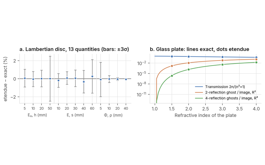
How close is the irradiance? Within a third of a percent everywhere, and within the noise of the random sampling. The ghost ratios of the plate agree to fourteen digits, because a reflection that is not too faint is followed deterministically.
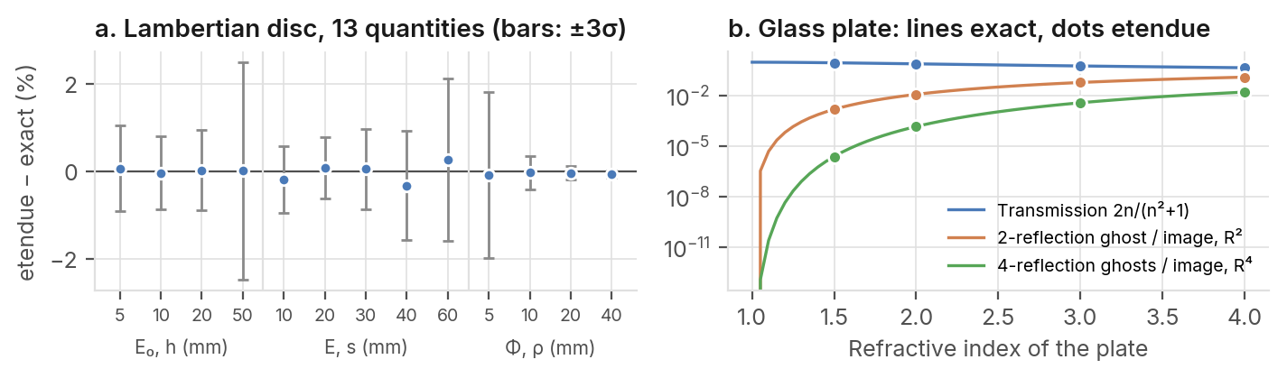
Figure 1. a. Relative difference between etendue and the exact value for the on-axis irradiance E₀ at four distances, the irradiance E(s) off axis at 20 mm, and the power Φ(ρ) within a radius ρ. b. Transmission and ghost-to-image ratios of the plate against its index. Image power for n = 1.5: 0.921600000000 of the source, exact 0.9216.
0.32% 2.6σ 0.001600 29 of 29
Largest difference from the Largest difference in units of Two-reflection ghost of an n = Comparisons within the limits
| exact irradiance or encircled | the Monte Carlo noise. All 13 | 1.5 plate relative to its image. | written before the |
| power, over 13 comparisons | lie within 3σ. | Exact: 0.0016. | measurement. |
on a Lambertian disc.
etendue.io References: Howell, Catalog of Configuration Factors; Hecht, Optics, § 4.6 · etendue, November 2026
The numbers, and what they do not say
Every comparison, the noise it was judged against, and what was not met.
Table 2. Lambertian disc, 5 mm radius, 1 W
Quantity Exact etendue Diff. (%) σ (%) Diff. / σ Verdict
On-axis irradiance, h = 5 mm 0.0062337 0.0062377 +0.06 0.33 +0.2 met
On-axis irradiance, h = 10 mm 0.0024619 0.002461 −0.04 0.28 −0.1 met
| On-axis irradiance, h = 20 mm | 7.2958×10⁻⁴ | 7.2976×10⁻⁴ | +0.03 | 0.30 | +0.1 met |
| On-axis irradiance, h = 50 mm | 1.2247×10⁻⁴ | 1.2248×10⁻⁴ | +0.01 | 0.83 | +0.0 met |
| Irradiance 10 mm off axis, h = 20 mm | 4.8812×10⁻⁴ | 4.8718×10⁻⁴ | −0.19 | 0.25 | −0.8 met |
| Irradiance 20 mm off axis, h = 20 mm | 1.9784×10⁻⁴ | 1.9800×10⁻⁴ | +0.08 | 0.23 | +0.3 met |
| Irradiance 30 mm off axis, h = 20 mm | 7.7040×10⁻⁵ | 7.7080×10⁻⁵ | +0.05 | 0.31 | +0.2 met |
| Irradiance 40 mm off axis, h = 20 mm | 3.2407×10⁻⁵ | 3.2303×10⁻⁵ | −0.32 | 0.41 | −0.8 met |
| Irradiance 60 mm off axis, h = 20 mm | 8.0233×10⁻⁶ | 8.0447×10⁻⁶ | +0.27 | 0.62 | +0.4 met |
Power within 5 mm radius, h = 20 mm 0.055728 0.05568 −0.09 0.63 −0.1 met
| Power within 10 mm radius, h = 20 mm | 0.19224 | 0.19218 | −0.03 | 0.13 | −0.2 met |
| Power within 20 mm radius, h = 20 mm | 0.49219 | 0.49199 | −0.04 | 0.05 | −0.8 met |
| Power within 40 mm radius, h = 20 mm | 0.79798 | 0.79746 | −0.07 | 0.03 | −2.6 met |
Irradiance in W/mm², averaged over the same detector cell as the exact value; power as a fraction of the emitted power. h: distance from the source to the plane. σ: Monte Carlo noise, from two independent draws of two million rays and from the binomial law. A value is met when it lies within 3σ of the exact one.
| Table 3. Glass plate, 400 rays: relative difference from the | Table 4. Transmission bias, 40 |
| exact value | independent draws |
n Transmission Image 2-refl. ghost 4-refl. ghosts n Mean diff. Std. error
1.5 −2.2×10⁻⁷ −8.1×10⁻¹⁵ 9.8×10⁻¹⁵ −8.4×10⁻² 1.5 1.3×10⁻⁷ 1.3×10⁻⁷
2 5.9×10⁻⁶ −6.7×10⁻¹⁵ 4.1×10⁻¹⁵ 4.1×10⁻² 2 −8.7×10⁻⁸ 6.8×10⁻⁷
3 8.0×10⁻⁶ 3.4×10⁻¹⁵ 0 0 3 8.1×10⁻⁷ 9.4×10⁻⁷
4 3.5×10⁻⁶ 8.4×10⁻¹⁵ −1.0×10⁻¹⁴ −5.8×10⁻¹⁵ 4 5.5×10⁻⁷ 1.2×10⁻⁶
Ghosts are counted relative to the image. In red: not met. A disc source of the same radius, 0.01° divergent, 500 rays per draw.
Where the noise is large fringes of a plate. A ray tracer sums powers, as does the
reference. The four-reflection ghosts of the n = 1.5 and 2 plates fall
^(b)^(e)^(l)^(o)^(w)^(1)^(0)^(⁻)^(⁴)^(o)^(f)^(t)^(h)^(e)^(s)^(o)^(u)^(r)^(c)^(e)^(,)^(w)^(h)^(e)^(r)^(e)^(f)^(a)^(i)^(n)^(t)^(r)^(e)^(f)^(l)^(e)^(c)^(t)^(i)^(o)^(n)^(s)^(a)^(r)^(e)^(e)^(n)^(d)^(e)^(d) How it was computed at random. They survive in 6 of 400 and 282 of 400 rays, so Each scene is built and traced as the non-sequential editor their value carries a large but known noise, and their does it, and read by the irradiance map, encircled energy, difference (−8%, +4%) lies within it. flux budget and ghost analyses of etendue. No value was
What this does not cover tuned. The 100-ray and 400-ray traces of the plate use
different random seeds, so that their difference measures Oblique incidence, where s and p polarisation reflect the noise of the random ending. Table 4 checks the differently, and coherent effects such as the Fabry-Perot transmission for a bias over 40 further independent draws.
References
[1] J. R. Howell, A Catalog of Radiation Heat Transfer Configuration Factors, 3rd ed., online, cases B-12, B-14, C-41; after H. C. Hottel, Trans. ASME 53 (1931) 265-273, and D. C. Hamilton, W. R. Morgan, NACA TN 2836 (1952). [2] E. Hecht, Optics, 5th ed., Pearson (2017), § 4.6, reflectance at normal incidence.