
Laser beam shaping
Thermal limits of a freeform ring-shaping head for a multimode fibre laser
Laser welding head at 1030 nm, ring of 3 / 2 mm diameter, laser power from 6 kW to 40 kW
Thermal limits of a freeform ring-shaping head for a
multimode fibre laser
Laser welding head at 1030 nm, ring of 3 / 2 mm diameter, laser power from 6 kW to 40 kW
| Application | Modelling approach |
| In a welding head, a freeform mirror turns the beam of a | We modelled the head from the fibre face to the work |
| fibre laser into a ring on the work piece. At several | piece, with its coatings, mounts and water cooling. The |
kilowatts the optics absorb part of the beam and heat up, ring is traced with real rays from the whole fibre face,
| and the ring grows and loses energy. This note asks how | through the hot optics at each laser power. We accept |
| much power the head can take, and what limits it. | the ring if at least 85 % of the power falls inside it, and if |
its uniformity, diameter and width stay within tolerance.
1 The head
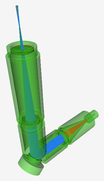
Figure 1. The head as modelled in etendue. A lens collimates the beam from the fibre. A copper freeform mirror, folded at 45° on a water-cooled block, shapes it. A second lens focuses the ring through a protective window. Table 1. Main parameters.
| PARAMETER | VALUE | PARAMETER | VALUE |
| Laser power | 6 kW | Collimating lens focal length | 150 mm |
| Wavelength | 1030 nm | Focusing lens focal length | 300 mm |
| Fibre core, numerical aperture | 200 μm, 0.1 | Ring outer diameter | 3 mm |
| Beam parameter product | 8 mm·mrad | Ring width | 0.5 mm |
2 The ring against laser power in specification up to 10 kW
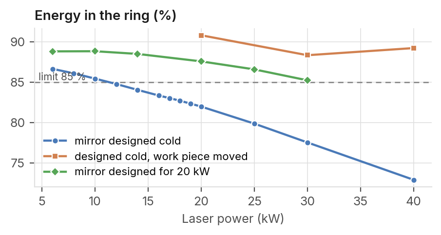
^(H)Th^(o)e^(w)r^(f)in^(a)g^(r)^(c)g^(a)r^(n)ow^(t)^(h)s^(e)w^(p)i^(o)th^(w)t^(e)h^(r)e^(g)h^(o)e^(?)a^(W)t,^(i)a^(t)^(h)nd^(t)^(h)a^(e)t^(m)12^(i)^(r)k^(r)^(o)W^(r)^(d)o^(e)n^(s)ly^(i)^(g)8^(n)4^(e).^(d)8^(f)%^(o)^(r)o^(c)f^(o)t^(l)h^(d)e^(o)p^(p)o^(t)^(i)w^(c)^(s)e^(,)r^(u)f^(p)all^(t)s^(o)i^(1)n^(0)si^(k)d^(W)e^(.)it. 10 kW Highest power with the mirror
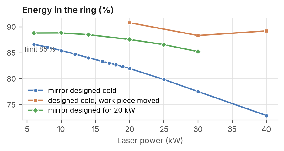
designed for cold optics, Gaussian heat model.
40 kW
With the work piece 3 mm closer
to the window.
6 to 30 kW
With a mirror designed for 20 kW.
40 ppm
Figure 2. Energy in the ring against laser power. With the work piece moved, each Window absorption accepted at 6 power has its own best position. kW, 2 times the clean coating.
3 What limits the power
What limits the power? The protective window. It absorbs about as much as each lens, but it loses its heat only through its rim, and the ring shaper concentrates the beam on its axis. The cooling circuits are not the limit. Once the stray light is traced into the hot state, the tube that holds the fibre limits first (page 2).
| 39 K | 7 K | 30 W | 6 μm |
| Temperature rise of the | Temperature rise of the | Heat removed by the water- | Growth of the ring diameter |
| window at 6 kW. | warmest lens at 6 kW. | cooled mirror block at 6 kW. | per kW. |
etendue.io 6 kW continuous laser, 1030 nm · 200 μm fibre · ring 3 / 2 mm · etendue, October 2026
What limits the power, and what to change
The protective window heats far more than the lenses. Moving the work piece or designing the mirror
for the hot optics extends the range.
Table 2. The ring at each laser power
Why the window limits the power
Used Outer at diameter Energy Criteria The window is cooled only at its rim, into a holder Mirror designed for (kW) (mm) Uniformity (%) met without water cooling. The ring shaper also cold optics 0 3.042 0.197 87.9 4 of 4 concentrates the beam on the axis where it crosses the window. The window becomes a thermal lens, cold optics 6 3.077 0.164 86.6 4 of 4 and the ring grows by about 6 μm per kW. cold optics 10 3.099 0.161 85.4 4 of 4 A dirty window absorbs more. At 6 kW the ring stays cold optics 12 3.111 0.163 84.8 3 of 4
| 20 kW | 0 | 2.924 | 0.226 | 88.5 | 4 of 4 |
| 20 kW | 6 | 2.956 | 0.213 | 88.8 | 4 of 4 |
| 20 kW | 10 | 2.977 | 0.194 | 88.8 | 4 of 4 |
| 20 kW | 14 | 2.999 | 0.178 | 88.5 | 4 of 4 |
| 20 kW | 25 | 3.056 | 0.156 | 86.6 | 4 of 4 |
| 20 kW | 30 | 3.090 | 0.154 | 85.2 | 4 of 4 |
in specification up to 40 ppm per face, 2 times the clean coating.
What does not help
Better cooling. With weaker water cooling of the mirror, the ring still meets its criteria at 6 kW. Cooling the window holder changes nothing, because silica conducts heat too poorly. cold optics, moved −3 mm 40 3.018 0.199 89.2 4 of 4
What helps
Criteria: energy at least 85 %, outer diameter within 5 %, width within 10 %, Moving the work piece towards the window brings uniformity below 0.25 (a limit chosen for this demonstration). Blue rows: the ring back. The range reaches 40 kW, one power mirror designed for the hot optics at 20 kW. Last row: work piece moved towards the window. at a time.
A mirror designed for the hot optics at 20 kW meets
Table 3. Heat to remove all criteria from 6 to 30 kW, and with cold optics too.
Laser power Absorbed by the Removed by the mirror Window rise
(kW) optics (W) block (W) (K) Conclusion
| 6 | 19 | 30 | 39 | Treat the protective window as the critical part. |
| 10 | 31 | 50 | 65 | Specify its coating absorption, and replace it before |
40 ppm per face. Cool the tube that holds the fibre. The mirror block also takes the light from the edge of the fibre that misses
| ^(t)^(h)^(e)^(m)^(i)^(r)^(r)^(o)^(r)^(,)^(1)^(2)^(W)^(a)^(t)^(6)^(k)^(W)^(.) | Stray light heats the head |
| Heat of the stray light, coated head | ^(T)^(h)^(e)^(c)^(o)^(a)^(t)^(i)^(n)^(g)^(r)^(e)^(f)^(l)^(e)^(c)^(t)^(i)^(o)^(n)^(s)^(a)^(d)^(d)^(0)^(.)^(0)^(3)^(W)^(a)^(r)^(o)^(u)^(n)^(d)^(t)^(h)^(e)^(r)^(i)^(n)^(g)^(,) |
but 2.2 W return near the fibre core (÷9 with the
| 35 W | 12 kW | 5 kW | window tilted 2°). Traced into the hot state, they |
| On the uncooled | Highest power, | Highest power, heat | heat the tube that holds the fibre: at 6 kW the fibre |
moves 67 μm and the ring widens. The Gaussian tube next to the fibre Gaussian heat of the traced light. model puts this heat on the cooled mirror block. at 6 kW: +20 K. model.
Figure 3. The ring on the work piece for each design, power and window
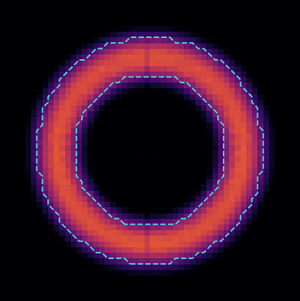
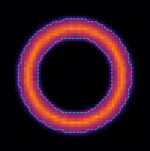
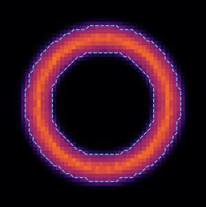
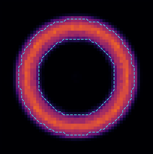
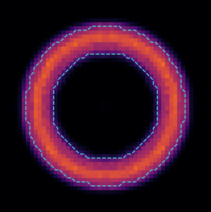
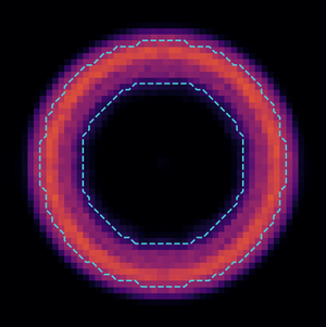
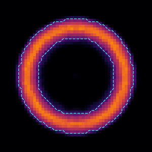
Designed for a point Designed for the Hot, 6 kW Hot, 18 kW Dirty window, 80 Hot, 40 kW 40 kW, work piece source real fibre 86.6 % · 3.08 mm 82.7 % · 3.14 mm ppm at 6 kW 72.9 % · 3.27 mm moved −3 mm 83.9 % · 3.00 mm 87.9 % · 3.04 mm 82.7 % · 3.14 mm 89.2 % · 3.02 mm
Irradiance over ±2 mm, same colour scale for every map. The dashed lines mark the target ring. Under each map: energy in the ring, green when the ring meets all four criteria, red otherwise, then the outer diameter.