
Laser micromachining
Spot size and shape across the field of a galvo scanner with a telecentric F-theta lens
80 W femtosecond laser at 1030 nm, two-axis galvo head, ±18° scan field
Spot size and shape across the field of a galvo scanner
with a telecentric F-theta lens
80 W femtosecond laser at 1030 nm, two-axis galvo head, ±18° scan field
| Application | Modelling approach |
| In femtosecond micromachining, a galvo scanner moves | We modelled the machine from the laser output to the |
| the spot over the part through an F-theta lens. On axis | work piece, with the F-theta lens of a published patent. |
the spot is small and round. Towards the edge of the field The beam was propagated to the work piece at the
| it grows and stretches, and the machine builder usually | centre and at the edges of the field. The spot is given by |
| finds out on the test bench, after assembly. This note | its diameter along its long and short axes, measured as in |
| asks why the spot degrades at the edge, and what can | ISO 11146 (second-moment diameter). |
be done about it.
1 The machine
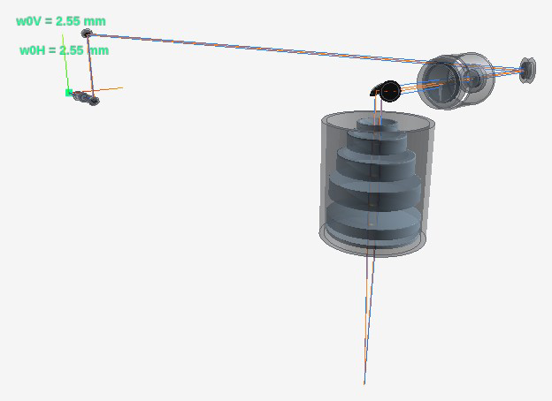
Figure 1. The machine as modelled in etendue, with its mechanical parts. A periscope carries the beam to a beam expander. Two galvo mirrors then steer it into the F-theta lens, which focuses it on the work piece. Table 1. Main parameters.
| PARAMETER | VALUE | PARAMETER | VALUE |
| Average power | 80 W | Expander magnification | 2 |
| Pulse energy, duration | 400 μJ, 290 fs | Galvo mirror aperture | 14 mm |
| Wavelength | 1030 nm | F-theta focal length | 165 mm |
| Beam transport to the galvos | 2.5 m | Scan field | ±18° |
2 The spot across the scan field
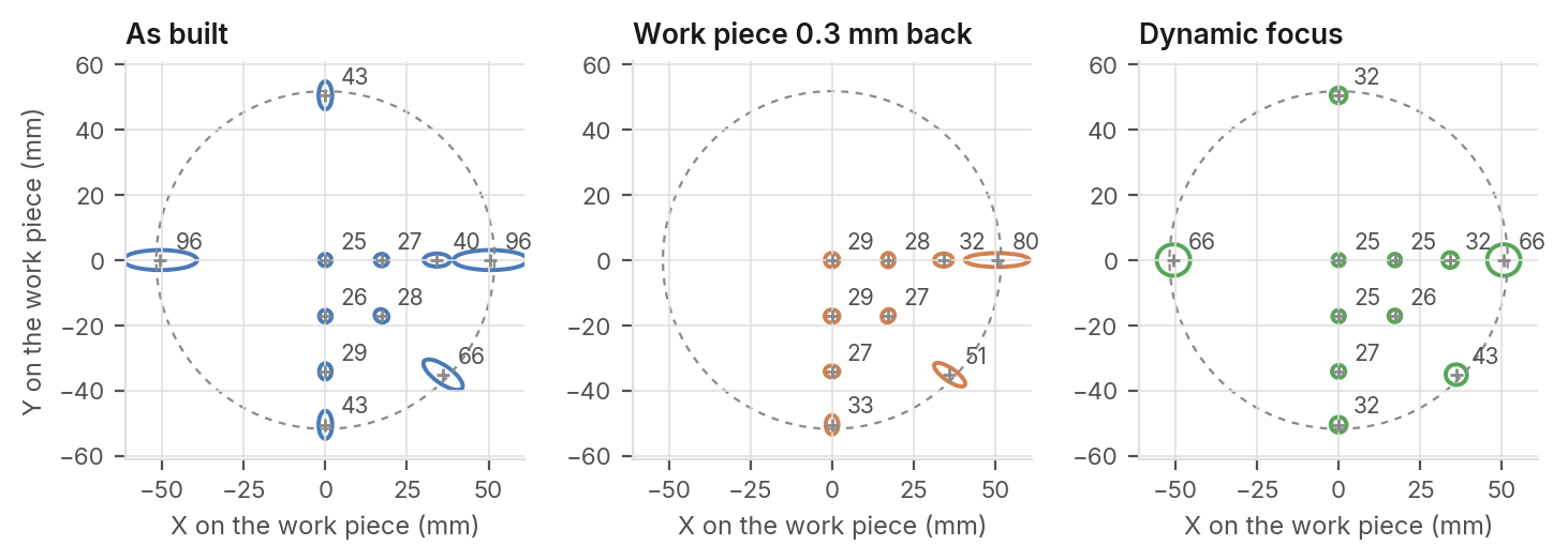
How does the spot change across the field? On axis it is round, 25 μm across. At the X edge it stretches to 151 × 41 μm, because its focus lies 2.2 mm behind the work piece. The Y edge suffers less. Three changes to the machine reduce the effect.
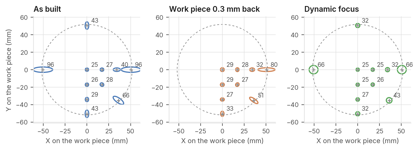
Figure 2. The spot at each scan position, drawn 150 times its real size, with its mean diameter in μm. Left: the machine as built. Centre: the work piece moved 0.3 mm further from the lens. Right: with a dynamic focus. The dashed circle is the ±18° field.
151 × 41 μm 42 → 37 μm 68 × 64 μm 65 → 94 %
| Spot at the X edge of the field, Mean spot over a quarter of | Spot at the X edge with a | Power passed by the galvo |
| long by short axis. On axis it is the field when the work piece | dynamic focus, which moves | mirrors at the X edge, before |
25 μm and round. is moved 0.3 mm further from the first expander lens by up and after enlarging the second
the lens. to 1.3 mm. mirror.
etendue.io 80 W, 200 kHz, 400 μJ, 290 fs, 1030 nm · ±18° scan field · etendue, October 2026
Why the spot degrades at the edge, and what to do
The two galvo mirrors see the F-theta lens from two different places. Neither sees a flat focal plane.
Table 2. Spot diameter across the field, long × short
axis (μm) Why the spot degrades
The F-theta lens does not focus on a flat plane. Seen
WORK POWER
AS PIECE 0.3 DYNAMIC PASSED from galvo X, at 18° the focus lies 2.16 mm off the work
SCAN POSITION BUILT MM BACK FOCUS (%)
piece along the scan and 0.46 mm across it. The Centre 25 × 25 29 × 29 25 × 25 97 Rayleigh range of the beam is 0.40 mm, so the spot at X, part way, 12° 54 × 27 38 × 27 32 × 32 85 the edge is far out of focus.
X edge, 18° 151 × 41 131 × 28 68 × 64 65 Seen from galvo Y, the error is smaller, 0.73 and 0.13 mm. The two mirrors sit 42 and 58 mm from the lens, so Y edge, 18° 57 × 28 40 × 26 32 × 32 97 each sees the lens differently. At the X edge the two foci Diagonal edge, 18° 95 × 36 76 × 26 43 × 42 84 are 1.7 mm apart. No focus setting removes this The angle is the scan angle on the work piece. The power passed is astigmatism; a lens designed for two mirrors would. the share that the two galvo mirrors let through.
What to do
Table 3. Effect of the expander magnification,
without dynamic focus^(M)^(o)^(v)^(i)^(n)^(g)^(t)^(h)^(e)^(w)^(o)^(r)^(k)^(p)^(i)^(e)^(c)^(e)^(0)^(.)^(3)^(m)^(m)^(f)^(u)^(r)^(t)^(h)^(e)^(r)^(f)^(r)^(o)^(m)^(t)^(h)^(e)^(l)^(e)^(n)^(s) costs nothing. The mean spot over the field drops from Spot, Power Power 42 to 37 μm, but the X edge stays at 131 × 28 μm. centre Spot, X passed, passed, X Magnification (μm) edge (μm) centre (%) edge (%) A dynamic focus moves the first expander lens by up to 1.5 34 118 × 43 100 76 1.3 mm. The X-edge spot becomes nearly round, 68 × 64 μm. 2 25 151 × 41 97 65 2.5 20 186 × 44 91 55 At the X edge the second galvo mirror cuts off part of the beam, and 65 % of the power reaches the work A wider beam focuses to a smaller spot, but its shorter Rayleigh range piece. A second mirror sized for the scan brings it back makes the edge worse, and the mirrors cut off more of it. to 94 %.
Other checks
At the edge, the spot lands 2.4 % short of the f·θ position, so the scanner needs a correction table. The peak fluence on the most exposed mirror is 0.0037 J/cm², well below the 0.2 to 0.7 J/cm² published for femtosecond mirrors. The heat absorbed at 80 W moves the focus by 19 μm at most.
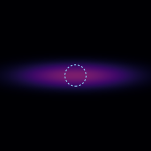
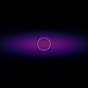
Figure 3. The spot on the work piece at each scan position, and at the X edge with each change
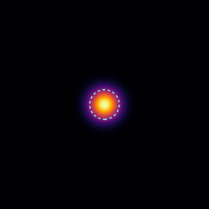
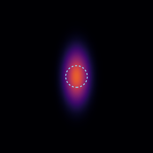
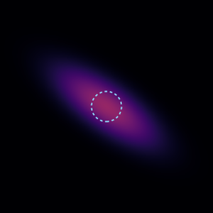

Diagonal Centre Y edge X edge edge 25 × 25 μm 57 × 28 μm 151 × 41 μm 95 × 36 μm 97 % passed 97 % passed 65 % passed 84 % passed

Work piece Larger
| The X edge with each | moved 0.3 | ^(D)^(y)^(n)^(a)^(m)^(i)^(c) | second |
| change. Compare with the | mm back | ^(f)6^(o)8^(c)×^(u)^(s)64 μm | mirror |
| spot as built, top right. | ^(1)6^(3)5^(1)%^(×)^(2)p^(8)as^(μ)s^(m)ed | 65 % passed | ^(1)9^(5)4^(1)%^(×)^(4)p^(1)a^(μ)ss^(m)ed |
Each map covers ±90 μm with the same colour scale, the square root of the irradiance. The dashed circle is the spot on axis. The percentage is the power that the two galvo mirrors pass.