
Automotive lighting · Projection optics
Projecting a micro-LED matrix headlamp: beam intensity, pixel separation and the dark zone around an oncoming car
256 × 64 pixels on a 50 µm pitch, imaged by the three-lens projection lens of patent US 11428378 (f = 30.4 mm, f/0.67), judged against UN Regulation No. 149
Projecting a micro-LED matrix headlamp: beam intensity,
pixel separation and the dark zone around an oncoming car
256 × 64 pixels on a 50 μm pitch, imaged by the three-lens projection lens of patent US 11428378
(f = 30.4 mm, f/0.67), judged against UN Regulation No. 149
| The design problem | How the system is modelled |
| In a micro-LED headlamp, each of several thousand | The lens is entered from the tables of patent US |
| pixels can be switched on or off. With all of them lit, the | 11428378, aspheres and stop included. The matrix is a |
| module gives a driving beam. When a car comes the | source of 16 384 Lambertian emitters, 45 μm square, |
| other way, the pixels aimed at its driver are switched off. | 0.4 lm each, and any set of pixels can be switched off. |
| The projection lens blurs each pixel, so some light of the | The rays leaving the lens are collected by direction into |
| lit pixels still reaches that dark zone. Lens design | an intensity map in candelas. The regulation is read on |
| describes the blur by a spot and an MTF in the matrix | that map. Each reading carries an error bound (three |
| plane, whereas UN Regulation No. 149 sets limits in | standard deviations of the Monte Carlo noise, plus the |
| candelas at given angles on the road. To check these | spread of the neighbouring cells). A requirement is met if |
| limits, the light of the pixels has to be traced through the | the whole bound respects the limit, not met if it violates |
| lens to the road. | it, and undetermined otherwise. |
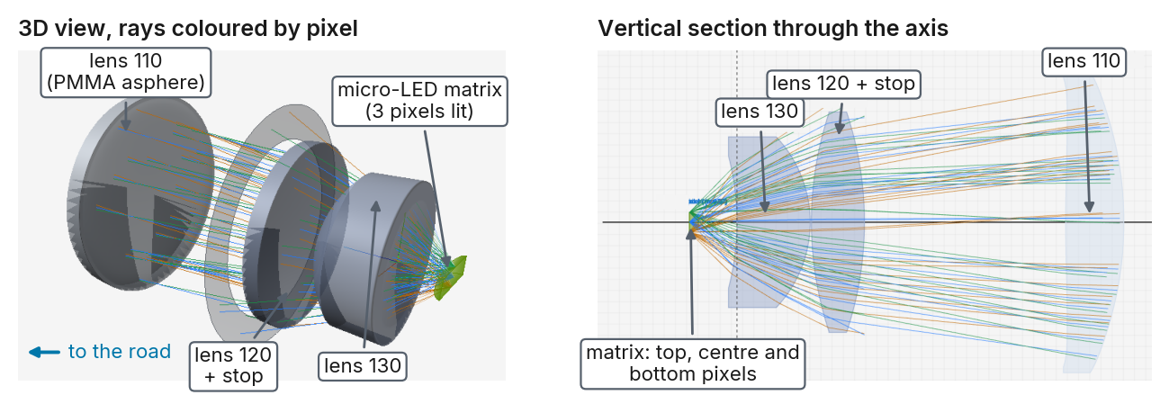
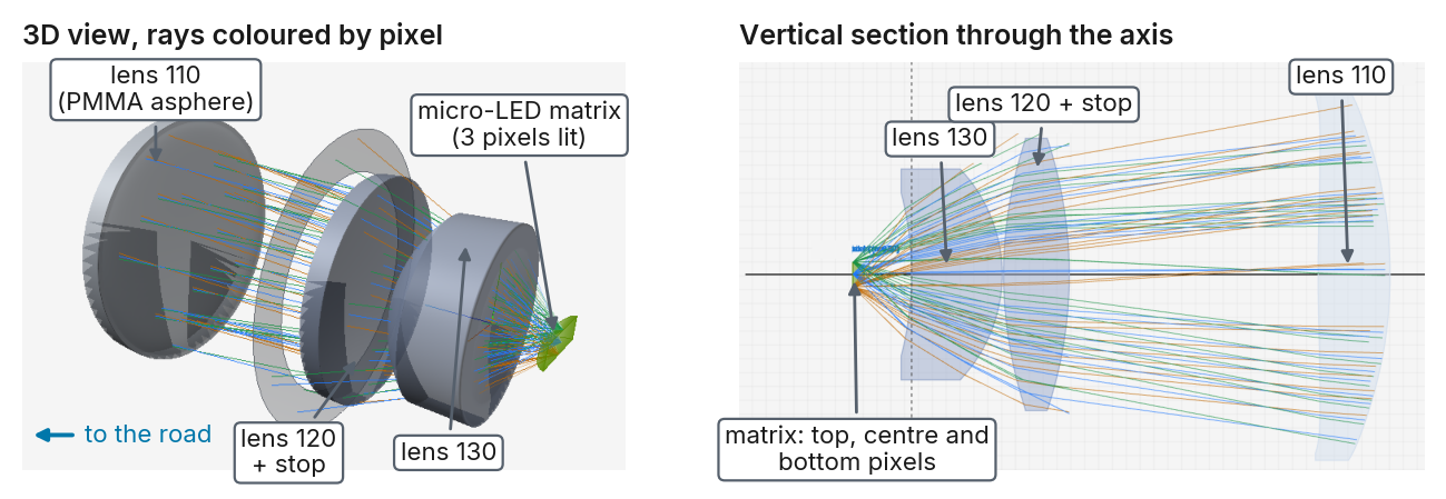
Figure 1. The model in etendue, with three pixels lit at the top, centre and bottom of the matrix. Each colour follows one pixel, from the matrix on the right towards the road.
What the analysis shows on the starting design One module with all pixels lit reaches a peak of 59000 cd, above the 40000 cd minimum of a class B driving beam. All 11 driving-beam requirements of the regulation are met, error bound included. The blur of the lens, however, is large compared with a pixel. The RMS spot diameter on the matrix is 1.7 pixel pitches at the centre and 6.3 at the left and right edges. A lit pixel at the centre should light a square of 0.094° on the road; it puts 20 % of its light there, 10 % in the square of the next pixel, and spreads the rest further out. Its own square is on average 1.3 times brighter than the brightest point of the next square, whose pixel is off.
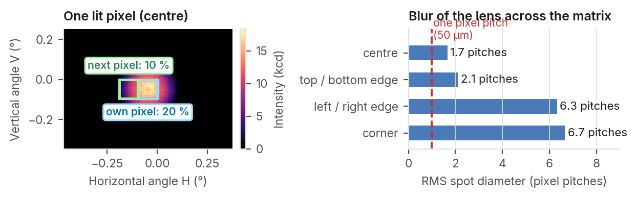
Figure 2. Left, intensity of one lit pixel computed by etendue, with its own angular square (blue) and that of the next pixel (green). Right, RMS spot diameter on the matrix (lens design model, 588 nm).
etendue.io 256 × 64 pixels · 50 μm pitch · f = 30.4 mm · non-sequential ray tracing · etendue, October 2026
The driving beam With all 16 384 pixels lit, the beam covers 24.6° by 6.1° and peaks at 59000 cd. All 11 driving-beam requirements are met, error bound included; the point straight ahead on the horizon reaches 0.99 times the peak.
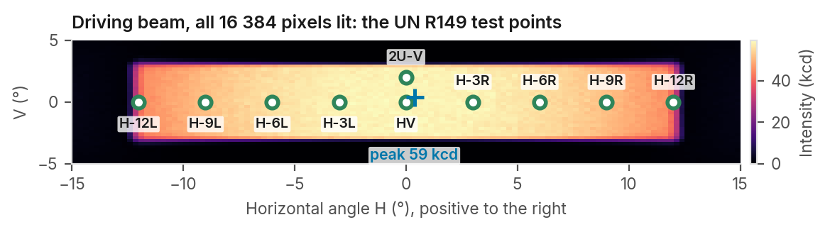
Figure 3. Intensity with all pixels lit, computed with etendue, and the UN R149 class B test points (green: met).
The dark zone for an oncoming car For an oncoming car at 50 m, the regulation allows 625 cd on a line through its driver's eyes. Switching off just the pixels aimed at it leaves up to 37 338 cd on it: the blur of the lit neighbours spills in. With three more columns off on each side (0.28° of beam), the line reads 28 cd, its error bound stays below 524 cd: met. With the stray light of a real module (four more columns), the line reads 537 cd, below the limit (756 cd, above, with a more dispersive PMMA): undetermined, as the largest single ray alone sets a bound of 1 616 cd and the cells next to the line read up to 920 cd. A ±2σ estimate of the noise alone (not a guarantee) reads “too few rays”.
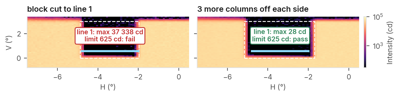
Figure 4. Intensity around the dark zone (log scale). Blue: the regulation line; dashed: the pixels switched off.
Light on the road A flat detector 0.65 m below the lens stands for the road. The beam reaches it from about 12 m ahead; the illuminance peaks at 15 lx at 13 m, and on the axis 1 lx reaches 33 m. The dark zone for the oncoming car aims above the horizon: switching it off changes the light on the road beyond 10 m by 0.05 %.
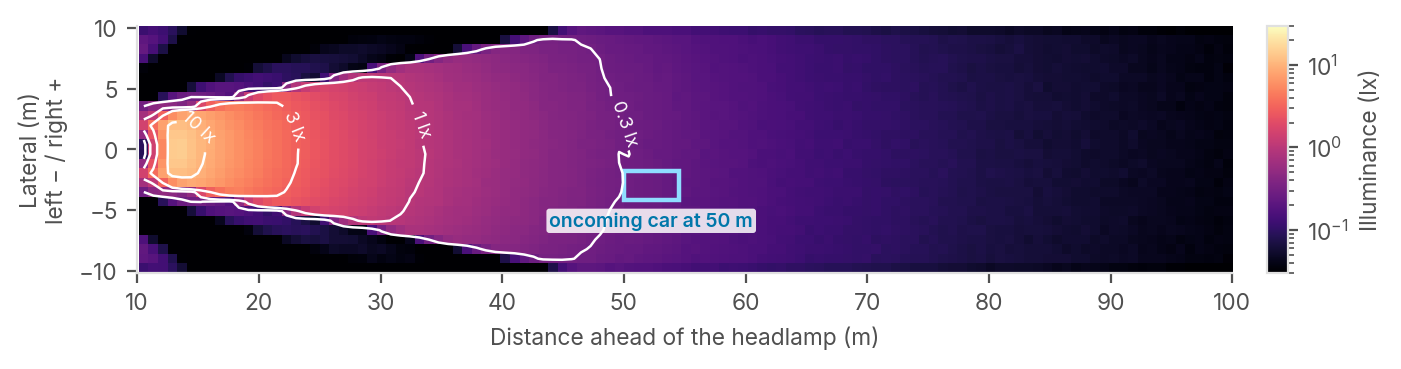
Figure 5. Illuminance on a level road seen from above, true scale, module 0.65 m high. White: equal-illuminance lines.
One plastic, and limitations Reliability of the results
All three lenses in PMMA, radii re-optimised: at 550 CHECK REFERENCE MODEL nm the central RMS spot diameter grows from 95 to f-number on axis 0.6 to 0.85 [1] 0.67 711 μm. One wavelength, 555 nm, for the maps of the First to last lens face 54 to 76 mm [1] 61.17 mm ideal module. 0.4 lm per pixel is 63 cd/mm², below Back focal distance at best focus 7.52 mm [1] 7.52 mm the 75–100 published [3]. No heating of the matrix. Total field 14–40° × 5–10° [1] 24.6° × 6.1°
Projection ratio, field H / V 2.5 to 6 [1] 4.0
References. [1] Patent US 11428378 B1, example 1. [2] UN Regulation No. 149, 01 series, § 5.1.4 and § 5.3. [3] Data sheets of automotive micro- LED matrices, 40 μm pitch.
etendue.io Driving beam, pixel separation, dark zone and road · non-sequential ray tracing · etendue