
Laser beam delivery · Harmonics
Lens spacing of a 3× beam expander used at 1030, 515 and 343 nm
Fused-silica singlets against CaF2 / fused-silica doublets for the three harmonics of a Yb laser, with the collimation read on the Gaussian beam at each line
Lens spacing of a 3× beam expander used at 1030, 515 and
343 nm
Fused-silica singlets against CaF2 / fused-silica doublets for the three harmonics of a Yb laser, with
the collimation read on the Gaussian beam at each line
| Application | Modelling approach |
| A micromachining station that switches between the | Two designs of the same 3× expander were compared. |
| fundamental, green and UV lines of a Yb laser needs a | Each was optimized on the three wavelengths at once, |
| collimated, three times wider beam at each line. In the | one variant per wavelength: the singlets keep their own |
| UV, fused silica and calcium fluoride are the lens | lens spacing at each line, the doublets share one |
| materials. The buyer asks whether one expander can | geometry. A Gaussian beam was then propagated |
| serve the three lines, and how far it must be adjusted. | through each case while the lens spacing was scanned. |
1 The two designs and the collimation at each line
| PARAMETER | VALUE |
| Laser\0lines | \0\0\0\0\0/\0\0\0\0\0/\0\0\0\0\0nm |
| Input\0beam | \0\0mm\0diameter\0\0\0/e²\0\0\0M²\0\0\0\0 |
Magnification \0\0\0\0fixed\0\0Galilean\0\0no\0internal\0focus\0
Singlet\0design two\0fused\0silica\0lenses
Doublet\0design two\0air\0spaced\0CaF\0\0/\0fused\0silica\0doublets
Housing\0length singlets\0\0\0\0\0mm\0at\0\0\0\0\0\0nm\0\0\0\0\0\0mm\0at\0\0\0\0 nm\0\0doublets\0\0\0\0\0mm
Table 1. Main parameters. The input aperture holds 99 % of the beam power.
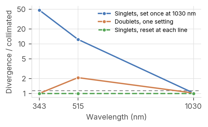
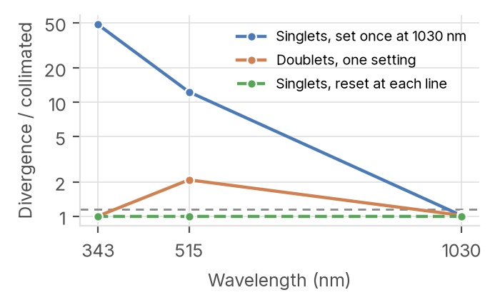
Figure 1. Divergence of the output beam divided by that of a perfectly collimated beam of the same diameter, at each line. The dashed line is the acceptance limit, 1.15.
2 The lens spacing each line needs
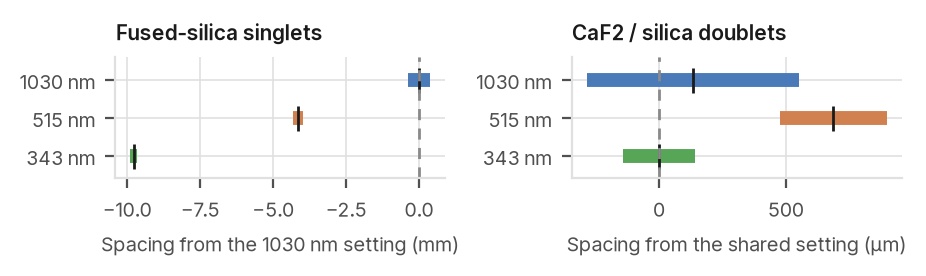
9.8 mm
How much closer the two singlets must be
at 343 nm than at 1030 nm \04.1 mm at 515
nm).
±115 μm
Spacing tolerance of the singlets at 343
nm, the tightest of the three lines. Figure 2. Range of lens spacing that keeps the collimation within the limit at each
line; the tick marks the best setting. Left, singlets, counted from the 1030 nm 687 μm
setting. Right, doublets, counted from the setting shared by 1030 and 343 nm. Extra spacing the doublets need at 515
nm; one setting serves 1030 and 343 nm.
Acceptance
A line is accepted when the magnification is within 1 % of 3, the divergence ratio stays below 1.15, and the wavefront error, focus removed, stays below λ/14 RMS \04\0. The 1.15 limit applies the same Maréchal criterion to the focus error alone; behind a focusing lens it keeps the focus within 0.56 Rayleigh lengths of its nominal position \03\0.
etendue.io 1030 / 515 / 343 nm · 3\0 Galilean · fused silica \01\0, CaF2 \02\0 · etendue, October 2026
Doublets cut the spacing travel from 10 mm to 0.7 mm
Magnification within 0.05 % in every collimated case; wavefront below λ/21 in every case.
Table 2. Each design at each line
Line Spacing Divergence / Divergence Wavefront Optical Design (nm) (mm) Magnification collimated (μrad) RMS spec
Singlets\0\0set\0once\0at\0\0\0\0\0\0nm \0\0\0\0 \0\0\0\0\0\0 \0\0\0\0\0 \0\0\0\0 \0\0 λ/\0\0\0 pass
\0\0\0 \0\0\0\0\0\0 \0\0\0\0\0 \0\0\0\0\0 \0\0\0 λ/\0\0 fail
\0\0\0 \0\0\0\0\0\0 \0\0\0\0\0 \0\0\0\0\0 \0\0\0\0 λ/\0\0 fail
Singlets\0\0reset\0at\0each\0line \0\0\0\0 \0\0\0\0\0\0 \0\0\0\0\0 \0\0\0\0 \0\0 λ/\0\0\0 pass
\0\0\0 \0\0\0\0\0\0 \0\0\0\0\0 \0\0\0\0 \0\0 λ/\0\0 pass
\0\0\0 \0\0\0\0\0\0 \0\0\0\0\0 \0\0\0\0 \0\0 λ/\0\0 pass
Doublets\0\0one\0setting \0\0\0\0 \0\0\0\0\0\0 \0\0\0\0\0 \0\0\0\0 \0\0 λ/\0\0 pass
\0\0\0 \0\0\0\0\0\0 \0\0\0\0\0 \0\0\0\0 \0\0 λ/\0\0 fail
\0\0\0 \0\0\0\0\0\0 \0\0\0\0\0 \0\0\0\0 \0\0 λ/\0\0 pass
Spacing: air gap between the lens groups. Divergence: half angle of the output Gaussian beam. Doublets at the spacing shared by 1030 and 343 nm.
| Singlets | Doublets | Recommendation |
| With one glass, both focal lengths | Calcium fluoride and fused silica | Doublets replace a 10 mm motorized |
| shrink together towards the UV. The | correct the colour between the two | focus with two fixed stops 0.7 mm |
| magnification stays at 3, but at 343 nm | ends of the band, 1030 and 343 nm, | apart. Singlets need three calibrated |
| the beam diverges 48 times more than | but not in the middle. At the shared | positions over 10 mm. |
| a collimated one. Moving the lenses 9.8 | setting the green beam diverges 2.1 |
| mm closer restores it, held to \0115 μm. | times more than a collimated one. |
Opening the spacing by 687 μm brings it back.
In etendue
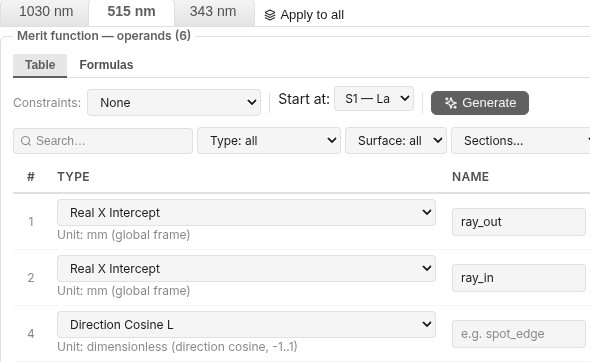
Figure 3. The merit function of the coupled optimization, variant 515 nm. Each wavelength is a variant with its own tab. The two named rows read the height of one real ray at the output and at the input; further down, a formula divides them and asks for a magnification of 3. The direction-cosine rows ask for a collimated output. Library project: « LAS12 \0 Beam Expander for the 1030, 515 and 343 nm Harmonics ».
References. \01\0 I. H. Malitson, Interspecimen comparison of the refractive index of fused silica, J. Opt. Soc. Am. 55, 1205 \01965\0. \02\0 I. H. Malitson, A redetermination of some optical properties of calcium fluoride, Appl. Opt. 2, 1103 \01963\0. \03\0 A. E. Siegman, Lasers, University Science Books \01986\0, ch. 17. \04\0 M. Born, E. Wolf, Principles of Optics, 7th ed., Cambridge University Press \01999\0, § 9.3 \0Maréchal criterion). Limits. Same input beam at the three lines; collimation read on the paraxial Gaussian beam. Aberration moves the best setting by 0.1 to 0.3 mm: a wave-optics propagation of the singlets at 343 nm gives a divergence ratio of 1.00 at the aberration-balanced setting and 1.15 at the paraxial one. Coatings and UV absorption not modelled.