
Laser powder bed fusion
Integrating lower-quality fibre lasers in an LPBF machine: spot size at the powder bed
1 kW fibre laser at 1070 nm, two-axis galvo head and F-theta lens, 250 × 250 mm build plate
Integrating lower-quality fibre lasers in an LPBF machine:
spot size at the powder bed
1 kW fibre laser at 1070 nm, two-axis galvo head and F-theta lens, 250 \0 250 mm build plate
| Application | Modelling approach |
| A laser powder bed fusion \0LPBF) process is qualified | We modelled the machine from the fibre collimator to the |
| with one laser. When a machine builder switches to a | powder bed. Four lasers are compared, with a beam |
| cheaper or different source, the beam quality is often | quality factor M² from 1.0 (a perfect beam) to 2.0. We |
| worse, and the spot on the powder bed grows. This note | count a laser as acceptable if its spot stays between 76 |
| answers a simple question: how much worse can the | and 127 μm everywhere on the plate, whether the optics |
| beam be before the process changes, and what does it | are cold or hot. |
take to fix it?
1 The machine
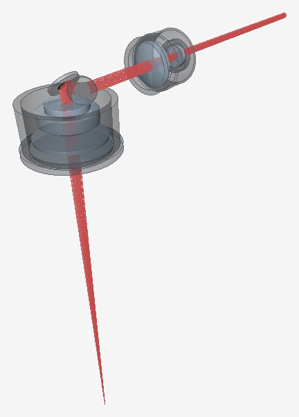
Figure 1. The machine as modelled in etendue. The expander enlarges the beam, two galvo mirrors steer it, and an F-theta lens from a published patent focuses it on the powder bed through a protective window. Table 1. Main parameters.
PARAMETER VALUE PARAMETER VALUE
Laser\0power \0\0\0\0\0W Expander\0magnification \0\0\0
| Process\0power | \0\0\0\0W | Galvo\0mirror\0aperture | \0\0\0mm |
| Wavelength | \0\0\0\0\0nm | F\0theta\0focal\0length | \0\0\0\0mm |
| Collimated\0beam\0diameter | \0\0mm | Build\0plate | \0\0\0\0\0\0\0\0\0\0mm |
2 Spot diameter against beam quality as built: up to M² 1.5
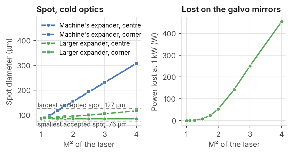
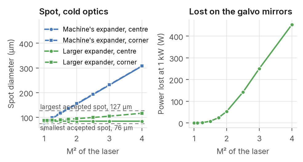
^(H)as^(o)^(w)it i^(f)s^(a),^(r)u^(c)p^(a)t^(n)o^(M)M^(²)²^(r)1^(i)^(s).5^(e).^(b)A^(e)l^(f)a^(o)r^(r)g^(e)er^(t)^(h)b^(e)e^(s)a^(p)m^(o)^(t)e^(l)x^(e)p^(a)a^(v)n^(e)d^(s)e^(t)r^(h)b^(e)r^(a)in^(c)g^(c)s^(e)^(p)th^(t)^(e)e^(d)sp^(r)^(a)o^(n)t^(g)b^(e)a^(?)c^(W)k t^(i)o^(t)^(h)it^(t)s^(h)^(e)re^(m)fe^(a)re^(c)n^(h)c^(i)^(n)e^(e) 85 μm Spot diameter of the reference size up to M² 1.75. Beyond that, the galvo mirrors cut off too much of the wider laser \0M² 1.1) at the centre of the beam. plate.
M² 1.5
The worst beam the machine
accepts as it is. Its spot is 115 μm
at the centre and 118 μm at the
edge.
M² 1.75
The worst beam the machine
accepts with a larger beam expander, which still passes
95 % of the power at the corner.
53 W
Lost on the galvo mirrors at 1 kW Figure 2. Left: spot diameter at the centre and at the corner of the plate, with the when an M² 2.0 laser is used with machine's expander and with an expander enlarged in proportion to M². The dashed its larger expander. lines mark the accepted range. Right: power lost on the galvo mirrors with the enlarged expander, at 1 kW.
etendue.io 1 kW, 1070 nm · process power 200 W · 250 mm plate · etendue, October 2026
Hot optics, dirty window, and what to change
Does the spot stay in range with hot optics and a dirty window? Up to M² 1.5 it does, at the cost of
more window changes.
Table 2. Spot diameter on the powder bed for each laser, at the 200 W process power
Cold, centre Cold, worst Hot, clean Hot, dirty Peak irradiance, cold Window absorption Laser (μm) edge (μm) window (μm) window (μm) \0MW/cm²\0 tolerated (ppm)
M²\0\0\0\0 \0\0 \0\0 \0\0 \0\0\0 \0\0\0 —
M²\0\0\0\0\0\0reference\0 \0\0 \0\0 \0\0 \0\0\0 \0\0\0 \0\0\0\0
M²\0\0\0\0 \0\0\0 \0\0\0 \0\0\0 \0\0\0 \0\0\0 \0\0\0
M²\0\0\0\0 \0\0\0 \0\0\0 \0\0\0 \0\0\0 \0\0\0 —
The accepted range is 76 to 127 μm. Hot: optics heated by the process beam, largest spot on the plate. The dirty window absorbs 1000 ppm \00.1 %) on its chamber side. The tolerated absorption is the one at which the spot leaves the range while a 20 \0 20 mm part is built (a dash: not computed, or out of range cold).
Why the spot grows
The spot diameter grows in proportion to M². At M² 1.5 the peak irradiance at 200 W is 3.8 MW/cm², against 6.8 MW/cm² with the reference laser.
Heat in the optics moves the focus. At 1 kW with a clean window, the focus moves 3.45 mm towards the lens when the beam is held at the centre. When the beam is scanned over the plate, the shift drops to 1.23 mm.
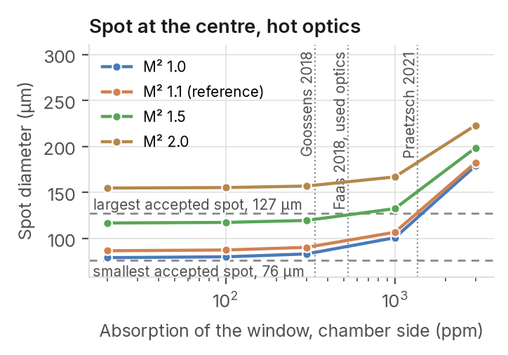
A dirty window absorbs more and makes the shift larger. While a typical part is built, the reference laser keeps its spot in range up to 2320 ppm of window absorption. The M² 1.5 laser leaves the range at 548 ppm.
Figure 3. Spot diameter at the centre of the plate as the
What to do
window absorbs more, optics heated by the 200 W beam. Up to M² 1.5, the laser goes into the machine as it is, but the The dotted lines place the focal shifts published for used protective window has to be replaced about 4 times as often. optics on this scale. From M² 1.5 to 1.75, a larger beam expander restores the
Table 3. Larger beam expander, cold optics reference spot \0Table 3\0. Beyond that, the galvo head and the
Spot, F-theta lens need a larger aperture. centre Spot, worst Power lost at Write the M² into the specification of any new laser. Power Laser Magnification (μm) edge (μm) 1 kW \0W\0 and scan speed do not show a change of spot size.
M²\0\0\0\0 \0\0\0\0 \0\0 \0\0 \0
M²\0\0\0\0 \0\0\0\0 \0\0 \0\0 \0\0
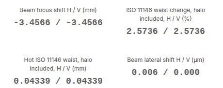
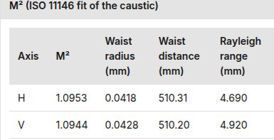
| Thermal lens at 1 kW, centre of the plate, clean window. Look | Beam quality at the edge of the plate, cold optics. Look at the |
| at the first tile: the focus moves 3.45 mm towards the lens. The | M² column. It reads 1.10 on both axes, as at the centre: the |
| waist radius grows from 42.3 to 43.4 μm. | galvo mirrors and the lens do not degrade the beam. |
Figure 4. Two results of the model in etendue, cropped to the values discussed in the text.