
Ophthalmic instrumentation
Correcting the aberrations of the eye in a retinal imager with a variable Zernike corrector
Schematic eye with an aberrated cornea, 3 mm pupil, 840 nm; corrector plate with 12 Zernike terms; ICNIRP exposure check
Correcting the aberrations of the eye in a retinal imager
with a variable Zernike corrector
Schematic eye with an aberrated cornea, 3 mm pupil, 840 nm; corrector plate with 12 Zernike terms;
ICNIRP exposure check
| The design problem | How the system is modelled |
| When an instrument images the retina through the pupil, | The eye is the schematic eye of Navarro [1] in its wide- |
| the aberrations of the eye blur the image of each | angle version [2]. Its anterior cornea carries two Zernike |
| photoreceptor. Adaptive optics corrects them, usually | terms of surface height, 2 μm and 1 μm, which add to the |
| with a deformable mirror driven by a wavefront sensor, a | aberrations of the eye itself. The eye, aberrated cornea |
| large and expensive assembly. A variable refractive | included, is a fixed input, and only the plate changes |
| corrector inside the instrument, such as a phase plate, a | during the design. As in an ophthalmoscope, light leaves |
| liquid lens or an Alvarez pair, is a cheaper alternative. | a point of the retina, crosses the eye and the corrector |
| The design must keep the wavefront error left by the | plate, and an ideal camera lens, which adds no |
| corrector small for each eye, and the light dose on the | aberration, images it on a detector. The corrector is a flat |
| retina within the safety limits. | glass plate whose front surface carries the Zernike terms |
OSA j = 3 to 14, which run from astigmatism and defocus to the fourth-order terms. The optimizer adjusts these 12 terms alone, with the RMS wavefront error at 840 nm as merit function.
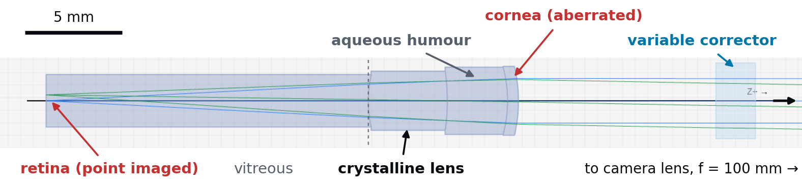
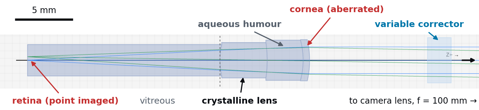
Figure 1. The eye and the corrector in the 2D view of etendue, at true scale. Light from a point of the retina crosses the eye, then the corrector plate; the camera lens and the detector lie further to the right.
What the analysis shows on the starting
design
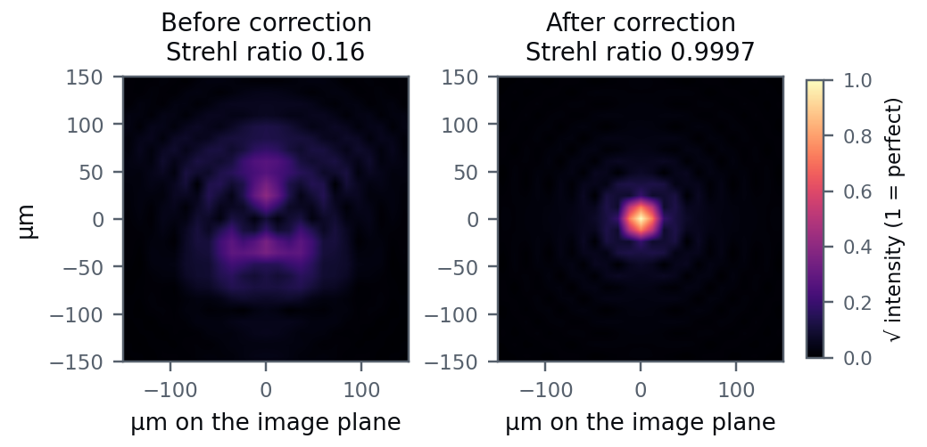
Before correction, the RMS wavefront error of the eye is 0.276 waves at 840 nm, and the Strehl ratio computed from the point spread function is 0.16. The largest terms are astigmatism, 0.17 waves, and secondary astigmatism, 0.12 waves. After one optimization of the corrector, the wavefront error falls to 0.0028 waves and the Strehl ratio rises to 0.9997. The twelve corrected terms keep a residual of 0.0009 waves RMS. Figure 2. Image of a point of the retina formed through the eye and the Terms beyond j = 14, which the plate cannot camera lens, before and after correction. Point spread functions computed reach, contribute 0.0026 waves, and the two add by etendue, shown as the square root of the intensity, on a scale where 1 is in quadrature to the total. Figure 2 shows the the peak of a perfect, diffraction-limited image. resulting image of a retinal point.
etendue.io 840 nm · 3 mm pupil · etendue, October 2026
Safety of the retinal illumination
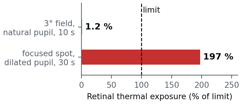
The exposure calculator of etendue compares the light sent into the eye with the exposure limits of the ICNIRP guidelines [5, 6]. A 1 mW source at 840 nm that lights a 3° field on the retina for 10 s reaches 1.2% of the retinal thermal limit. As a worst case, the same 1 mW is focused on one spot, a source of 1.5 mrad apparent size, the smallest the guidelines consider, through a pupil dilated to 7 mm as during an examination, for 30 s. The retina then receives 2.0 times the thermal limit set for ophthalmic instruments [6]. The calculator Figure 3. Retinal thermal exposure of the two illuminations, as a follows these guidelines; conformity with ISO 15004-2 share of the ICNIRP limit, from the exposure calculator of etendue. [7], the regulatory standard for ophthalmic instruments, is a separate assessment.
From the model to a real corrector
The optimized plate is described by 12 Zernike coefficients of surface height, the largest of which is 4.7 μm. A freeform phase plate would be made to these coefficients, and a programmable corrector would be set to them for this eye.
Reliability of the results
The table compares the eye models and the wavefront criteria with published results or exact formulas, and gives the largest differences. Outside the table, the largest gap is on the off-axis astigmatism of the wide-angle eye, 15% of the published value at 20° [2]; this note uses the axis only. One worked example is not reproduced because the guideline text contradicts itself. It prints 50 W/cm² as the retinal limit for a 26 μm image [6], while its own formula gives 46.2 W/cm².
| CHECK | RESULT | SOURCE |
| Power of the Navarro eye at 589 nm | 60.40 D against 60.4 D published | [1] |
| Chromatic aberration of the eye from 450 to 900 nm | largest difference 0.11 D from the chromatic eye of [3] | [3] |
| RMS wavefront of a Zernike surface of known height | largest difference 0.24 % from the exact value | exact formula |
| Strehl ratio for σ ≤ 0.1 wave RMS | largest difference 0.08 % from exp(−(2πσ)²) | [4] |
| Worked examples of the exposure limits | 12 of 13 reproduced | [5, 6] |
D: dioptres.
Limitations
One optimization run is limited to 9 minutes of computing time, and the result above used this full time on a workstation. There is no ready-made liquid lens or Alvarez component in etendue; they are built from a surface of variable curvature or from two polynomial plates moved sideways. This note treats one eye. Several eyes are handled as copies of the system that share the instrument and differ by the eye and by the corrector terms.
Use in teaching
The case is used as a design exercise in five stages. One loads a published eye, adds the aberrations of a measured eye, builds the instrument around it, optimizes the corrector on the wavefront and checks the illumination against the exposure limits.
References: [1] R. Navarro, J. Santamaría, J. Bescós, J. Opt. Soc. Am. A 2(8), 1273–1281 (1985). [2] I. Escudero-Sanz, R. Navarro, J. Opt. Soc. Am. A 16(8), 1881–1891 (1999). [3] L. N. Thibos, M. Ye, X. Zhang, A. Bradley, Appl. Opt. 31(19), 3594–3600 (1992). [4] V. N. Mahajan, J. Opt. Soc. Am. 73(6), 860–861 (1983). [5] ICNIRP, Health Phys. 105(1), 74–96 (2013). [6] ICNIRP, Appl. Opt. 44(11), 2162–2176 (2005). [7] ISO 15004-2:2024, ophthalmic instruments.
etendue.io Wavefront from real-ray tracing; Strehl ratio from the FFT point spread function.