
Laser beam delivery · High power
Collimation and thermal lens of a 1×–4× zoom beam expander at 1 kW
Galilean zoom with three fused-silica lenses, four zoom positions optimized together, 1030 nm continuous laser from 100 W to 1 kW
Collimation and thermal lens of a 1×–4× zoom beam
expander at 1 kW
Galilean zoom with three fused-silica lenses, four zoom positions optimized together, 1030 nm
continuous laser from 100 W to 1 kW
| Application | Modelling approach |
| A zoom beam expander sets the beam diameter, and | Each zoom position is a variant of the same system. The |
| therefore the focused spot, of a laser machine for | four positions were optimized together: each keeps its |
| cutting, drilling or micromachining. The machine builder | own lens spacings, while the lens shapes are shared. |
| needs the magnification shown on the dial to be the real | The magnification was written as a formula, the ratio of |
| one, the beam to leave collimated at every position, and | the output and input heights of a real ray. Each position |
| both to hold when the laser runs at full power. This note | was then heated by the laser until the temperature of |
| answers these questions for a 1 kW fibre laser. | every lens stopped changing. |
1 The expander at its four positions
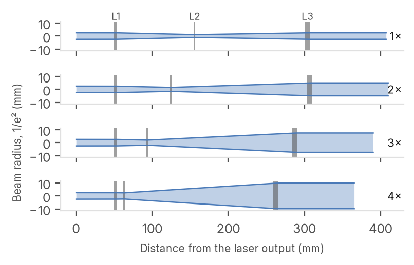
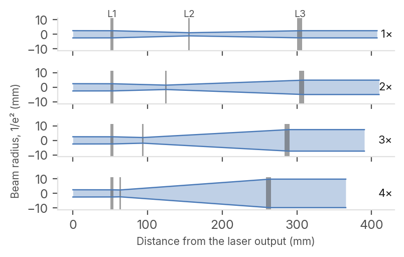
Figure 1. Beam radius through the expander at each position, with the three lenses in grey. The beam narrows between L1 and L2 but never comes to a focus: its smallest radius is 1.07 mm, at 1\0. Table 1. Main parameters.
| PARAMETER | VALUE |
| Laser | \0\0kW\0CW\0\0\0\0\0\0\0nm\0\0M²\0\0\0\0 |
| Input\0beam | \0\0mm\0diameter\0\0\0/e²\0 |
| Output\0beam | \0\0to\0\0\0\0mm\0diameter |
| Lenses | three\0\0fused\0silica\0\0AR\0coated |
| Moving\0lenses | L\0\0and\0L\0\0\0L\0\0fixed |
| Housing\0length | \0\0\0\0to\0\0\0\0\0mm |
2 Collimation from 100 W to 1 kW
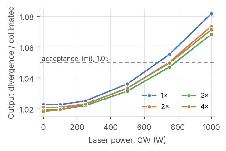
680 W
Highest power at which the output beam
stays collimated within 5 % at all four zoom
positions, without adjustment. The 1×
position limits it.
85 μm to 1.3 mm
Movement of L3 towards L2 that restores
collimation at 1 kW, from 4× to 1\0.
λ/80
Largest RMS wavefront error over the four
positions (at 4\0), far below the λ/14 of a
diffraction-limited beam.
Figure 2. Divergence of the output beam divided by the divergence of a perfectly collimated beam of the same diameter, against laser power, without any adjustment. The dashed line is the acceptance limit of this study.
etendue.io 1030 nm, 1 kW CW · 1\0, 2\0, 3\0, 4\0 · fused silica 3 ppm/cm, AR 20 ppm per face · etendue, October 2026
Optical specification met cold; above 680 W, L3 moves
Magnification within 0.2 %, wavefront below λ/80; the thermal lens of L2 sets the power limit.
Table 2. Each zoom position, cold
DIVERGENCE Why 1× limits the power
/ WAVEFRONT M² OPTICAL Each lens absorbs about 41 mW at 1 kW. The
POSITION MAGNIFICATION COLLIMATED RMS OUT SPEC
negative lens L2 sees the narrowest beam, so \0\0 \0\0\0\0\0 \0\0\0\0\0 λ/\0\0\0 \0\0\0\0 pass it heats the most, and most at 1\0, where the \0\0 \0\0\0\0\0 \0\0\0\0\0 λ/\0\0\0 \0\0\0\0 pass beam on it is smallest. Its weak positive thermal lens makes the output beam diverge \0\0 \0\0\0\0\0 \0\0\0\0\0 λ/\0\0\0 \0\0\0\0 pass about 5 % more than when cold. \0\0 \0\0\0\0\0 \0\0\0\0\0 λ/\0\0 \0\0\0\0 pass
Magnification: ratio of real-ray heights. Wavefront: RMS of a Zernike fit without Above the limit
piston, tilt and defocus. Input M²: 1.10. Acceptance: magnification within 1 %, Up to 680 W the expander needs no divergence ratio up to 1.05, wavefront up to λ/14, M² growth up to 5 %. adjustment. Above, moving L3 towards L2
Table 3. Each zoom position at 1 kW^(\0)a^(T)t^(a)e^(b)v^(l)e^(e)r^(3)y^())p^(b)o^(r)s^(i)^(n)it^(g)io^(s)n^(t).^(h)A^(e)m^(b)^(e)a^(a)te^(m)ria^(b)l^(a)w^(c)^(k)ith^(w)n^(i)^(t)e^(h)g^(i)^(n)at^(t)i^(h)v^(e)e^(l)^(i)^(m)^(i)^(t)
Hottest lens, Divergence / Power L3 shift After the dn/dT in the beam is the passive alternative Position L2 \0K\0 collimated limit (μm) shift \03\0.
\0\0 \0\0\0\0 \0\0\0\0\0 \0\0\0\0W \0\0\0\0\0 \0\0\0\0\0
\0\0 \0\0\0\0 \0\0\0\0\0 \0\0\0\0W \0\0\0\0 \0\0\0\0\0 Ghosts
Each double reflection carries about 4 mW at 1
\0\0 \0\0\0 \0\0\0\0\0 \0\0\0\0W \0\0\0\0 \0\0\0\0\0
kW. All focus in air except one, inside L2 near
\0\0 \0\0\0 \0\0\0\0\0 \0\0\0\0W \0\0\0 \0\0\0\0\0
3\0\0 harmless at a few milliwatts of continuous
| Rise at the centre of L2, the hottest lens. Power limit: where the divergence ratio | power, but a pulsed laser would call for |
| reaches 1.05. L3 shift: movement that gives the hot beam its smallest divergence; | another lens bending. Transmission: 98.8 %. |
negative is towards L2.
In etendue
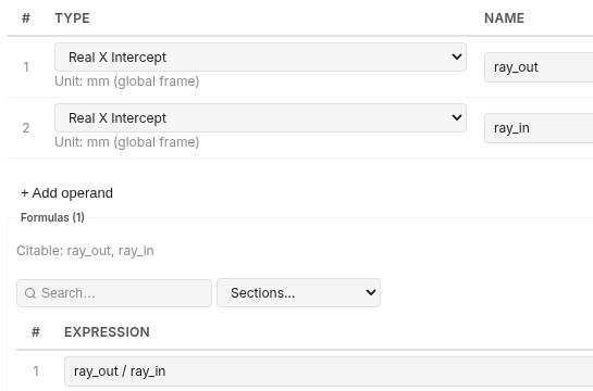
Figure 3. Left, the merit function of the coupled optimization, variant 4\0. The two named rows read the height of one real ray at the output and at the input, with weight 0. The formula row divides them, with target 4 and weight 100. Below, the expander at 4× in the viewer. Library project: « LAS09 \0 High-Power Zoom Beam Expander 1x- 4x ».

References. \01\0 US 5,134,523 \0Galilean zoom beam expander). \02\0 A. E. Siegman, Analysis of laser beam quality degradation caused by quartic phase aberrations, Appl. Opt. 32\030\0, 5893 \01993\0. \03\0 M. Stubenvoll, B. Schäfer, K. Mann, Measurement and compensation of laser-induced wavefront deformations and focal shifts in near IR optics, Opt. Express 22\021\0, 25385 \02014\0. \04\0 M. Born, E. Wolf, Principles of Optics, Cambridge University Press \0Maréchal criterion, λ/14 RMS\0. Limits. Absorption from data sheets, lenses cooled by air only, acceptance limits chosen for this study.