
Ultrafast laser optics · Nonlinear propagation
B-integral and pulse duration in a 0.5× to 1.7× ultrafast zoom beam expander
Three-lens Galilean zoom behind a 1030 nm femtosecond laser, 7 variants, pulse propagated through the real system at each position
B-integral and pulse duration in a 0.5× to 1.7× ultrafast
zoom beam expander
Three-lens Galilean zoom behind a 1030 nm femtosecond laser, 7 variants, pulse propagated through
the real system at each position
| Application | Modelling approach |
| A zoom beam expander sets the spot size of a | The pulse of the laser was propagated through the lens |
| femtosecond micromachining head. Its lenses also add a | prescription at each zoom position. The dispersion of |
| nonlinear phase to every pulse, and that phase grows as | every glass and air gap gives the output duration, and |
| the beam gets smaller. This note finds the highest pulse | the beam size along the path gives the nonlinear phase, |
| energy that each zoom position accepts before the | the B-integral. A position is accepted while the B-integral |
| spectrum of the pulse starts to change, and the pulse | stays below 1 rad, the value under which the spectral |
| duration at the output. | change is insignificant [1]. |
1 The zoom and its positions
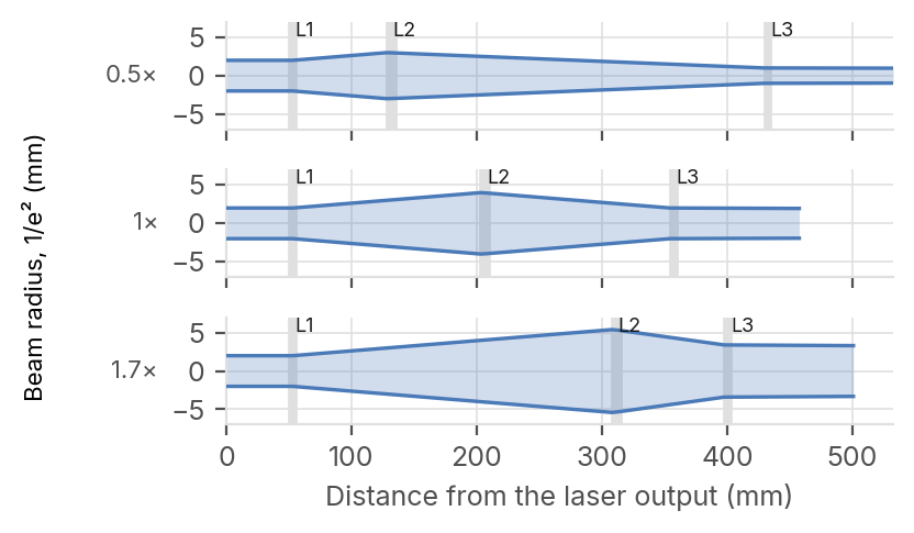
Figure 1. Beam radius along the zoom at its three positions, laser on the left; grey bands are the lenses: the negative first lens (fixed), the positive second lens and the negative last lens (both moving). The beam stays at least as wide as the input beam until the last lens. Table 1. The laser and the zoom as modelled.
PARAMETER VALUE
Laser 1030 nm, 300 fs sech², 100 μJ at 200 kHz
Input beam radius 2.0 mm at 1/e², M² 1.2
| Lenses | f = −150 / +150 / −150 mm, fused silica |
| Zoom | L1 fixed; L2, L3 move; 308–383 mm |
long
Positions 0.5×, 1×, 1.7×
2 Nonlinear phase at each zoom position
837 μJ
Highest pulse energy at the 0.5× position for
a B-integral of 1 rad. The 1× and 1.7×
positions accept 2 018 μJ and 3 093 μJ.
64 %
Share of the B-integral taken by the last lens
at 0.5×, where it carries the reduced output
beam.
302 fs
Output pulse duration at that energy, for a
300 fs input: dispersion and self-phase modulation leave the duration unchanged.
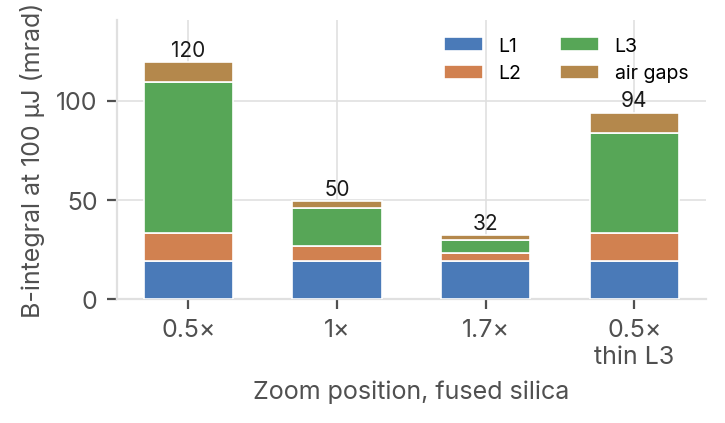
Figure 2. B-integral of a 100 μJ pulse at each zoom position, split between the three lenses and the air gaps. The last bar is the 0.5× position with a thinner last lens (2 mm instead of 3 mm).
etendue.io 1030 nm, 300 fs · B-integral limit 1 rad [1] · etendue, October 2026
The last lens sets the energy limit
The smallest beam of the zoom is the output beam at 0.5×, inside the last lens.
Table 2. Energy accepted at each zoom position
Why the reduction limits
Output B at L3 Highest radius 100 μJ share energy Duration Within The first lens sees the input beam at every Variant (mm) (mrad) (%) (μJ) (fs) 10 % position and takes the same share of the B- 1× fused silica 2.0 50 38 2 018 303 pass integral. The last lens carries the output beam: at 0.5× its radius is halved and its intensity is 0.5× fused silica 1.0 120 64 837 302 pass four times higher. At 0.5× it takes 64 % of the 1.7× fused silica 3.4 32 20 3 093 304 pass total. The air gaps add 8 %. 0.5× BK7-type crown 1.0 129 64 776 302 pass
1× BK7-type crown 2.0 53 39 1 869 304 pass What raises the limit
A last lens of 2 mm instead of 3 mm raises the 1.7× BK7-type crown 3.4 35 21 2 866 305 pass energy accepted at 0.5× from 837 μJ to 1 062 0.5× fused silica, thin L3 1.0 94 54 1 062 302 pass μJ. A BK7-type crown instead of fused silica Highest energy: B-integral of 1 rad, glass and air. Duration: FWHM of the output lowers it to 776 μJ. pulse at that energy (300 fs input). Output radius at 1/e²; L3: last lens.
Above the critical power
Table 3. Kerr lens at the highest energy of each position
The peak power is 59 times the critical power Peak index Energy Shortest Kerr focal Output beam for self-focusing at 100 μJ, and 496 times at Position (μJ) change (×10⁻⁶) length (m) narrowing (%) the limit of the 0.5× position. The beam does 0.5× 837 35 2.4 (L3) 2.1 not collapse: the glass path stays below 8 % of the self-focusing distance [2].
1× 2 018 21 15.7 (L3) 0.7
^(1)^(.)^(7)^(×)^(3)^(0)^(9)^(3)^(3)^(2)^(1)^(0)^(.)^(3)^(()^(L)^(1)^())^(0)^(.)^(4) Conclusion
Fused silica. Largest on-axis index change of the three lenses; narrowing of the With a 4 mm beam and 300 fs pulses, this beam radius at the output plane. zoom accepts up to 837 μJ at every position without pre-compensation, with an unchanged pulse duration. Above, avoid the 0.5× position or thin its last lens (1 062 μJ with 2 mm).
Figure 3. Dispersion at the 1× position
In etendue
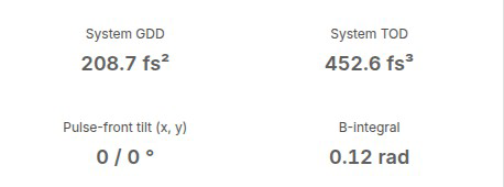

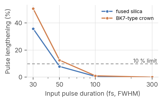
The zoom adds 209 fs² of group-delay dispersion in fused silica and 276 fs² in BK7-type crown, at every Figure 4. Results at 0.5× and 100 μJ: Laser pulse (top), Kerr effect position. A 300 fs pulse is not lengthened; a 50 fs pulse (bottom; S2, S4, S6: L1, L2, L3). The zoom positions are variants of the comes out at 54 fs, a 30 fs pulse at 41 fs. library project « LAS10 - Ultrafast Zoom Beam Expander ».
Limits of the study. Gaussian beam without clipping; laser values are assumptions of this study [4]; the 10 % duration limit is a choice of this study; thermal effects of the average power and the coatings are not included. References. [1] S. Yu. Mironov et al., 100 J-level pulse compression for peak power enhancement, Quantum Electron. 47, 173 (2017). [2] V. Arévalo, A. Becker, Phys. Rev. A 72, 043807 (2005), Dawes-Marburger law; critical power after G. Fibich, A. L. Gaeta, Opt. Lett. 25, 335 (2000). [3] n2 of fused silica: S. R. Flom et al., Appl. Opt. 54, F123 (2015). [4] Laser parameters of the order of P. Balage et al., Micromachines 14, 1650 (2023).