
Athermalising a three-channel camera: focus drift by channel, flange material and temperature gradient
Cassegrain telescope with a 2.15 m entrance pupil, split by two dichroic plates into three cameras from 360 to 1 000 nm, f/4.25, operated from −11 to 32 °C
Athermalising a three-channel camera: focus drift by channel, flange material and temperature gradient Cassegrain telescope with a 2.15 m entrance pupil, split by two dichroic plates into three cameras from 360 to 1 000 nm, f/4.25, operated from −11 to 32 °C
The design problem
A multi-channel camera splits the light of one telescope with dichroic plates and images each band on its own detector through its own focal reducer. Over an operating range of 43 °C, the glasses change index and the metal parts change length, so each channel drifts out of focus by an amount that depends on both. A classical lens design file computes each channel on its own, at one tem-
perature, with the mechanics reduced to air gaps. The choice of the flange material that holds each reducer cannot be judged that way
How the system is modelled
A multi-channel camera splits the light of one telescope The telescope, the two dichroic plates tilted at 45° and with dichroic plates and images each band on its own the three reducers of 3 lenses form one optical system, detector through its own focal reducer. Over an operating with one configuration per channel. The 7 mechanical range of 43 °C, the glasses change index and the metal parts of each reducer expand along published curves parts change length, so each channel drifts out of focus [2], with a flange in aluminium 6061, titanium Ti-6Al-4V by an amount that depends on both. A classical lens de- or Invar 36. From −11 to 32 °C, the lens spacings follow sign file computes each channel on its own, at one tem- the parts and the glass indices follow their thermo-optic perature, with the mechanics reduced to air gaps. The coefficients. The criterion is the peak-to-peak focus drift choice of the flange material that holds each reducer at the worst of four wavelengths of the band, against the cannot be judged that way. depth of focus 2·N·p = 93.5 μm (f/4.25, 11 μm pixels).
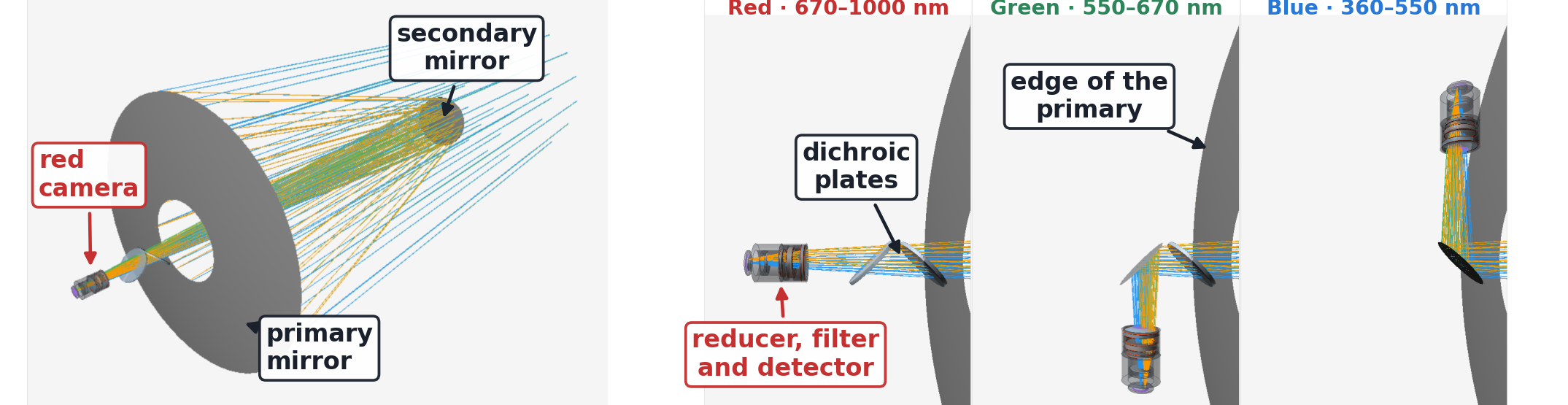
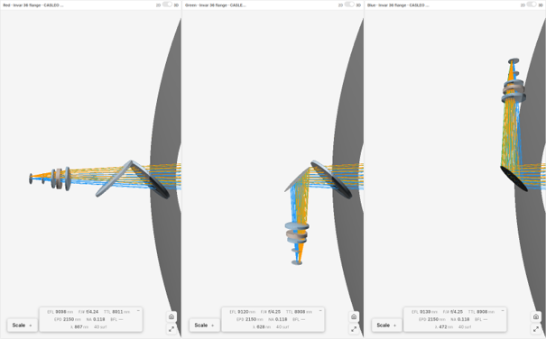
Figure 1. The model in the etendue lens design software. Left, the telescope with the rays of the red channel. Right, the three channels with their mechanical parts. One of the two plates reflects the green and blue beams, and the red beam crosses both.
What the analysis shows on the starting design
With an aluminium flange, the three channels stay in focus, with drifts of 43, 33 and 12 μm for red, green and blue. A tita- nium flange raises them to 88, 79 and 60 μm. With Invar 36, the red and green channels drift by 117 and 108 μm, beyond the depth of focus, and the blue channel stays inside at 90 μm. The aluminium barrel and spacers lengthen with tempera- ture and offset part of the change of the glasses. A flange that expands less removes part of that offset.
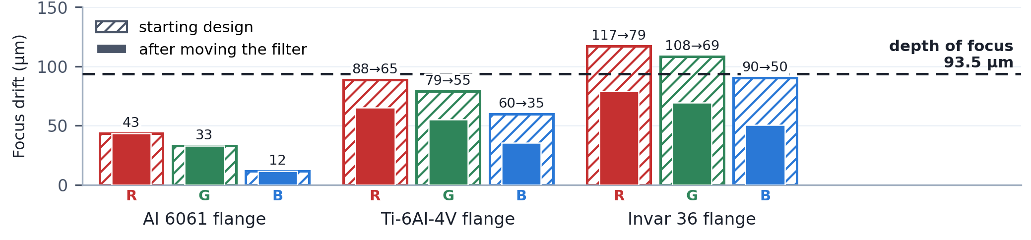
Figure 2. Peak-to-peak focus drift from −11 to 32 °C at the worst wavelength, computed by etendue for each channel and flange material. Hatched, the starting design. Solid, after the filter is moved (page 2). Dashed, the depth of focus.
One mechanical degree of freedom
The filter sits between the flange, which holds it behind the last lens, and the aluminium holder that carries the detector. Moving the filter along the beam changes how much of each metal lies between the last lens and the detector, which both stay in place. The optimizer varies this one position, with a merit function on spot size and focus at −11, 20 and 32 °C and a bound that keeps at least half of the Invar flange. It moves the filter towards the last lens until the flange reaches that bound (79.2 to 39.6 mm in the red channel). The drift then falls to 79.0, 69.3 and 50.3 μm with Invar and to 65.1, 55.1 and 35.3 μm with titanium, and does not change with aluminium. All nine combinations are within the depth of focus. The image at 20 °C does not change, since the filter keeps its thickness.
Freeing the 6 radii of the three lenses as well lowers the merit function by a further 9.8, 8.3 and 6.2 % (red, green, blue), but the on-axis spot of the red channel at 20 °C grows from 6.76 to 7.81 μm.
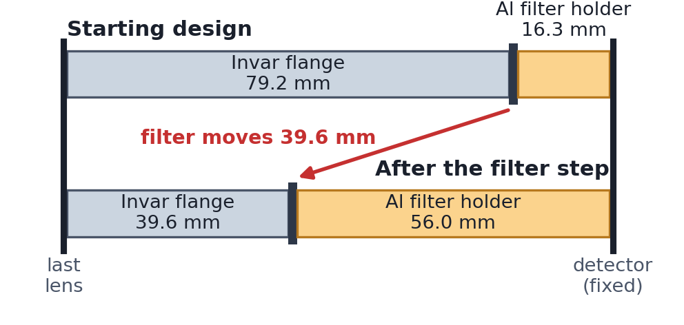
Figure 3. Red channel, Invar flange. Lengths before and after the red channel).
A temperature difference across the instrument
Two further cases warm or cool one side of the instrument, on the design after both optimisations. On the hot face, the housing parts are 10 °C and the spacers and lenses 5 °C above the uniform temperature. On the cold face, they are 4 and 2 °C below. The gradient shifts the focus by nearly the same amount at every temperature (4.5 to 4.6 μm in the red chan- nel, hot face), so the peak-to-peak drift changes by 0.57 μm at most. At 20 °C, the on-axis spot changes by 4.9 % (red, hot face) and the worst spot of the field by less than 3 %.

Figure 4. Left, focus position of the red channel with the Invar flange, worst wavelength, for a uniform temperature and for each face warmer or colder. Right, focus shift due to the gradient at 20 °C in each channel.
Bores and manufacturing data
The bore of each mechanical part is checked against the traced beam at every temperature and wavelength, with a 5 % clearance. The spacer between the first two lenses, of different diameters, is bored as a cone from Ø 101 to Ø 88 mm. No part cuts the beam, and every lens, filter and window blank passes the manufacturing check.
Limitations
The mechanics are not published and were declared for this study, so the absolute drifts depend on them. One glass of the reducer has no published thermal data and is replaced by a close substitute. Each part has a uniform temperature. The hot face is a deliberate worst case, and the cold face corresponds to radiative cooling under a clear night sky [3]
Reliability of the results
The prescription follows the published design [1], which gives no thermal data. The thermal model was checked against two calculations made outside etendue, and the spots, traced with 12 rings of rays, against a finer trace.
References.
[1] Nájera et al., Rev. Mex. Astron. Astrofís. (2026), arXiv:2605.11329, tables 1, 4 and 5.
[2] Y. S. Touloukian et al., Thermophysical Properties of Matter, TPRC Data Series vol. 12, Thermal Expansion: Metallic Elements and Alloys (1975).
[3] arXiv:2010.01978